UNO+WiFi R3 ATmega328P+ESP8266, 32Mb flash, USB-TTL CH340G, Micro-USB
Overview
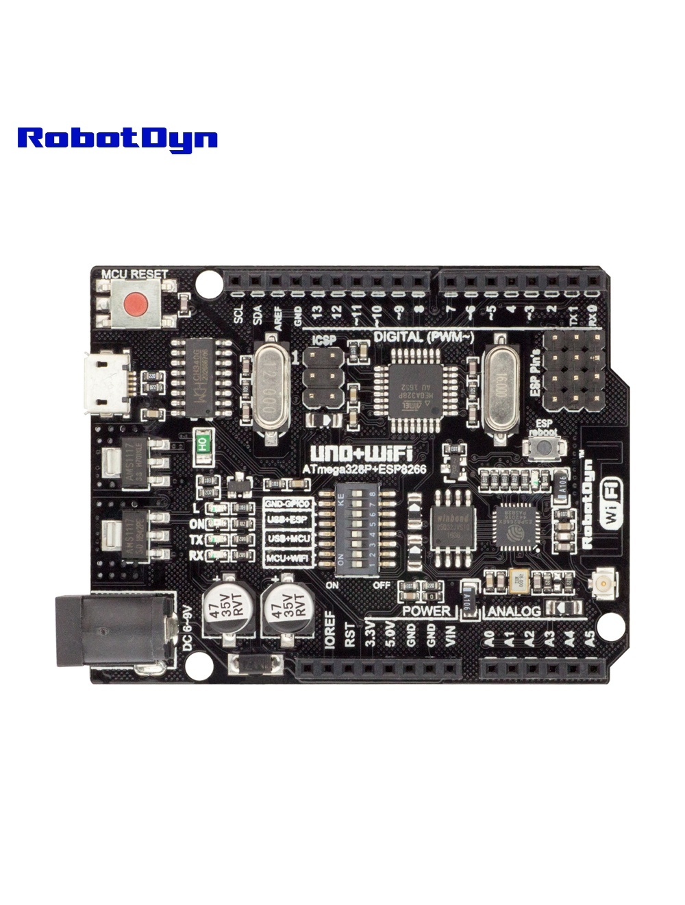
The RobotDyn UNO+WiFi R3 combines an Arduino UNO R3 (ATmega328P) with an ESP8266EX Wi-Fi module on a single shield-compatible board. Both MCUs share a CH340G USB-TTL converter for programming over a single Micro-USB cable.
Unlike Wi-Fi shields, the ESP8266 here is a full microcontroller with its own 32 Mb (4 MB) of flash — enough to run web servers, MQTT clients, or OTA-updatable firmware independently of the ATmega.
Why Use This Board
For IoT projects where you want UNO-level simplicity but need Wi-Fi without sacrificing shield compatibility. The board fits standard Arduino UNO shields (with awareness — see warnings below) while adding wireless connectivity.
Compared to standalone ESP8266 boards (like NodeMCU): you get 5 V I/O on the ATmega side (compatible with most existing Arduino sensors and shields), plus more reliable real-time control.
DIP Switch Configuration
The 8-position DIP switch (from the original RobotDyn documentation):
| Mode | 1 | 2 | 3 | 4 | 5 | 6 | 7 | 8 |
|---|---|---|---|---|---|---|---|---|
| CH340 → ESP8266 (upload firmware) | OFF | OFF | OFF | OFF | ON | ON | ON | — |
| CH340 → ESP8266 (connect/serial monitor) | OFF | OFF | OFF | OFF | ON | ON | OFF | — |
| CH340 → ATmega328 (upload sketch) | OFF | OFF | ON | ON | OFF | OFF | OFF | — |
| ATmega328 ↔ ESP8266 (independent USB) | ON | ON | OFF | OFF | OFF | OFF | OFF | — |
| All independent (no connections) | OFF | OFF | OFF | OFF | OFF | OFF | OFF | — |
DIP 8 is reserved (unused).
Programming
ESP8266 Setup in Arduino IDE
To program the ESP8266 side, install the ESP8266 board package:
- File → Preferences → Additional Boards Manager URLs, add:
http://arduino.esp8266.com/stable/package_esp8266com_index.json - Tools → Board → Boards Manager, search esp8266 by ESP8266 Community, install (version 2.1.0+)
- Tools → Board → Generic ESP8266 Module
- Tools → Upload Speed → 115200
Upload to ATmega328P (Uno)
- Set DIP 3, 4 = ON; rest OFF
- Tools → Board → Arduino Uno
- Upload as normal
Upload Firmware to ESP8266
- Set DIP 5, 6, 7 = ON to enter flash mode
- Press the ESP Reboot button before upload
- Upload from Arduino IDE
- Return DIP 7 = OFF to run normally
MCU-to-MCU Serial
Set DIP 1, 2 = ON. ATmega’s hardware Serial (pins 0/1) connects to ESP8266’s UART. The board includes voltage level shifters on this line.
Note: Because the ESP8266 shares pins 0/1 (RX/TX) with the ATmega’s USB serial, you cannot easily debug via
Serial.print()while ESP communication is active. Use SoftwareSerial on other pins for debugging, or disable DIP 1, 2 temporarily.
Example: ATmega controls ESP8266 LED via Serial
This sketch (from the original RobotDyn documentation) configures the ESP8266 as a TCP server on port 5000 and toggles an LED on pin 14 (A0) based on received characters:
void setup() {
  Serial.begin(115200);
  pinMode(14, OUTPUT);
  delay(500);
  Serial.println("AT+CIPMUX=1");
  delay(2000);
  Serial.println("AT+CIPSERVER=1,5000");
  delay(2000);
  Serial.println("AT+CIPSTO=3600");
  delay(2000);
}

void loop() {
  while (Serial.available()) {
    char Rdata;
    Rdata = Serial.read();
    if (Rdata == 'A' || Rdata == 'a') {
      digitalWrite(14, HIGH);
      delay(50);
    } else if (Rdata == 'B' || Rdata == 'b') {
      digitalWrite(14, LOW);
      delay(10);
      digitalWrite(14, HIGH);
      delay(10);
      digitalWrite(14, LOW);
    } else {
      digitalWrite(14, LOW);
    }
  }
}
Set DIP 1, 2 = ON to bridge ATmega↔ESP, upload, then telnet to the board’s IP on port 5000.
Logic Level Warning
The ATmega328P side runs at 5 V, but the ESP8266 is 3.3 V tolerant only. The board includes voltage level shifters on the inter-MCU communication lines, but if you’re wiring external sensors to ESP8266 GPIOs, do not exceed 3.3 V on those pins.
Common Uses
- IoT sensor nodes with cloud upload
- Smart home modules (relay control + MQTT)
- Web-controlled servos / steppers
- Local LAN dashboards for sensor data
- OTA-updatable embedded controllers
Where to Buy in 2026
Compatible clones are widely available on AliExpress and Amazon. Look for boards with CH340G (not CH340T or older variants) and 32 Mb flash to match this exact configuration.
Related Products
- MEGA+WiFi R3 — bigger sibling with 54 I/O pins
Documentation
- Pinout PDF — coming soon
- DIP switch reference — coming soon
- Schematic — coming soon