MEGA+WiFi R3 ATmega2560+ESP8266, flash 32MB, USB-TTL CH340G, Micro-USB
Overview
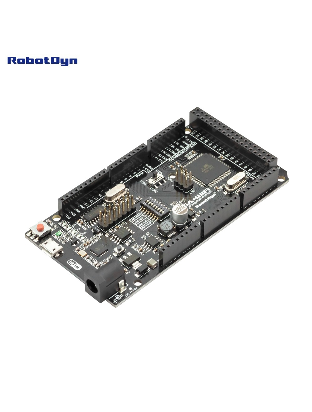
The RobotDyn MEGA+WiFi R3 combines a full Arduino Mega 2560 (ATmega2560) with an ESP8266EX Wi-Fi module on a single Arduino Mega-form-factor board. The two microcontrollers can operate independently or communicate with each other via UART, configured through an 8-position DIP switch.
A single CH340G USB-TTL converter handles programming for both MCUs — no external programmer or FTDI cable needed.
Why Use This Board
For projects that need both Arduino’s I/O power (54 digital pins, 16 analog, 15 PWM) and Wi-Fi connectivity without stacking a shield. The ESP8266 has its own 32 Mb flash, enough for serving web interfaces or OTA firmware updates while the ATmega handles real-time control.
DIP Switch Configuration
The 8-position DIP switch routes USB to one of two targets, links the two MCUs together, or isolates everything.
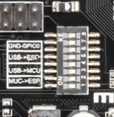
Use this table from the original RobotDyn documentation:
| Mode | 1 | 2 | 3 | 4 | 5 | 6 | 7 | 8 |
|---|---|---|---|---|---|---|---|---|
| CH340 → ESP8266 (upload firmware) | OFF | OFF | OFF | OFF | ON | ON | ON | — |
| CH340 → ESP8266 (connect/serial monitor) | OFF | OFF | OFF | OFF | ON | ON | OFF | — |
| CH340 → ATmega2560 (upload sketch) | OFF | OFF | ON | ON | OFF | OFF | OFF | — |
| Mega2560 COM3 ↔ ESP8266 | ON | ON | ON | ON | OFF | OFF | OFF | — |
| Mega2560 ↔ ESP8266 (independent USB) | ON | ON | OFF | OFF | OFF | OFF | OFF | — |
| All independent (no connections) | OFF | OFF | OFF | OFF | OFF | OFF | OFF | — |
DIP 8 is reserved (unused).
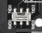
There’s also a switch to change which connection port routes between the ATmega2560 and the ESP8266:
Programming
ESP8266 Setup in Arduino IDE
To program the ESP8266 side, you first need the ESP8266 board package installed in Arduino IDE.
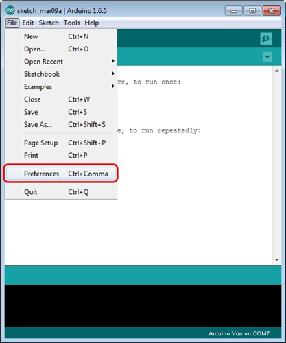
1. Open File → Preferences:
2. Paste this URL into Additional Boards Manager URLs:
http://arduino.esp8266.com/stable/package_esp8266com_index.json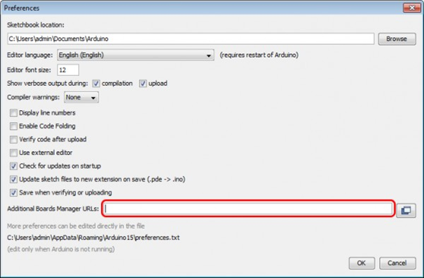
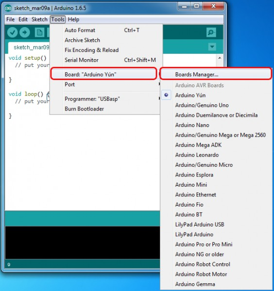
3. Open Tools → Board → Boards Manager:
4. Search for esp8266 by ESP8266 Community:
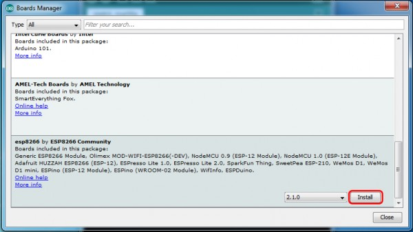
5. Select version 2.1.0 or later and click Install:
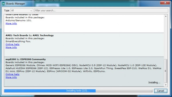
6. After installation, the ESP8266 boards appear under Tools → Board:
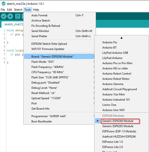
7. Select Generic ESP8266 Module:
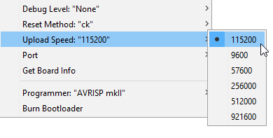
8. Set Tools → Upload Speed → 115200:
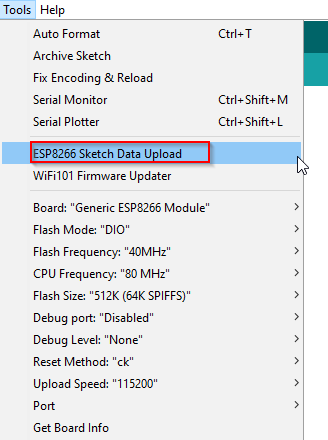
Upload to ATmega2560
- Set DIP 3, 4 = ON; rest OFF
- Tools → Board → Arduino Mega 2560
- Select serial port and upload
Upload Firmware to ESP8266
-
Set DIP 5, 6, 7 = ON; rest OFF (puts ESP in flash mode)
-
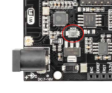
Press the Mode button on the board when starting upload (some board revisions):
-
Upload from Arduino IDE
-
After upload, set DIP 7 = OFF to run normally
MCU-to-MCU Communication
Set DIP 1, 2 = ON (Mega ↔ ESP via Serial3). ATmega’s Serial3 (pins 14 TX / 15 RX) is hard-wired to the ESP8266’s UART. Use Serial3.print() and Serial3.read().
Example: ATmega2560 controls ESP8266 LED via Serial3
This sketch (from the original RobotDyn documentation) runs on the ATmega2560, sets up the ESP8266 as a TCP server, then turns the onboard LED on/off based on characters received over WiFi:
void setup() {
  Serial3.begin(115200);
  pinMode(13, OUTPUT);
  delay(500);
  Serial3.println("AT+CIPMUX=1");
  delay(2000);
  Serial3.println("AT+CIPSERVER=1,5000");
  delay(2000);
  Serial3.println("AT+CIPSTO=3600");
  delay(2000);
}

void loop() {
  while (Serial3.available()) {
    char Rdata;
    Rdata = Serial3.read();
    if (Rdata == 'A' || Rdata == 'a') {
      digitalWrite(13, HIGH);
      delay(50);
    } else if (Rdata == 'B' || Rdata == 'b') {
      digitalWrite(13, LOW);
      delay(10);
      digitalWrite(13, HIGH);
      delay(10);
      digitalWrite(13, LOW);
    } else {
      digitalWrite(13, LOW);
    }
  }
}
Set DIPs as listed above (Mega2560 ↔ ESP8266), upload to the Mega, then telnet to the board’s IP on port 5000 and send “A” or “B” to control the LED.
Common Uses
- IoT data loggers (ATmega reads sensors, ESP uploads to cloud)
- Smart home controllers with web UI on ESP, hardware control on ATmega
- Remote-controlled robotics with web dashboard
- MQTT bridges with rich GPIO
Where to Buy in 2026
Original RobotDyn production has ended. Identical clones are widely available — the design is open-source. Look for boards explicitly marked with CH340G and 32 Mb flash to match the original.