WiFi Module ESP-01, ESP8266, 8Mb
Overview
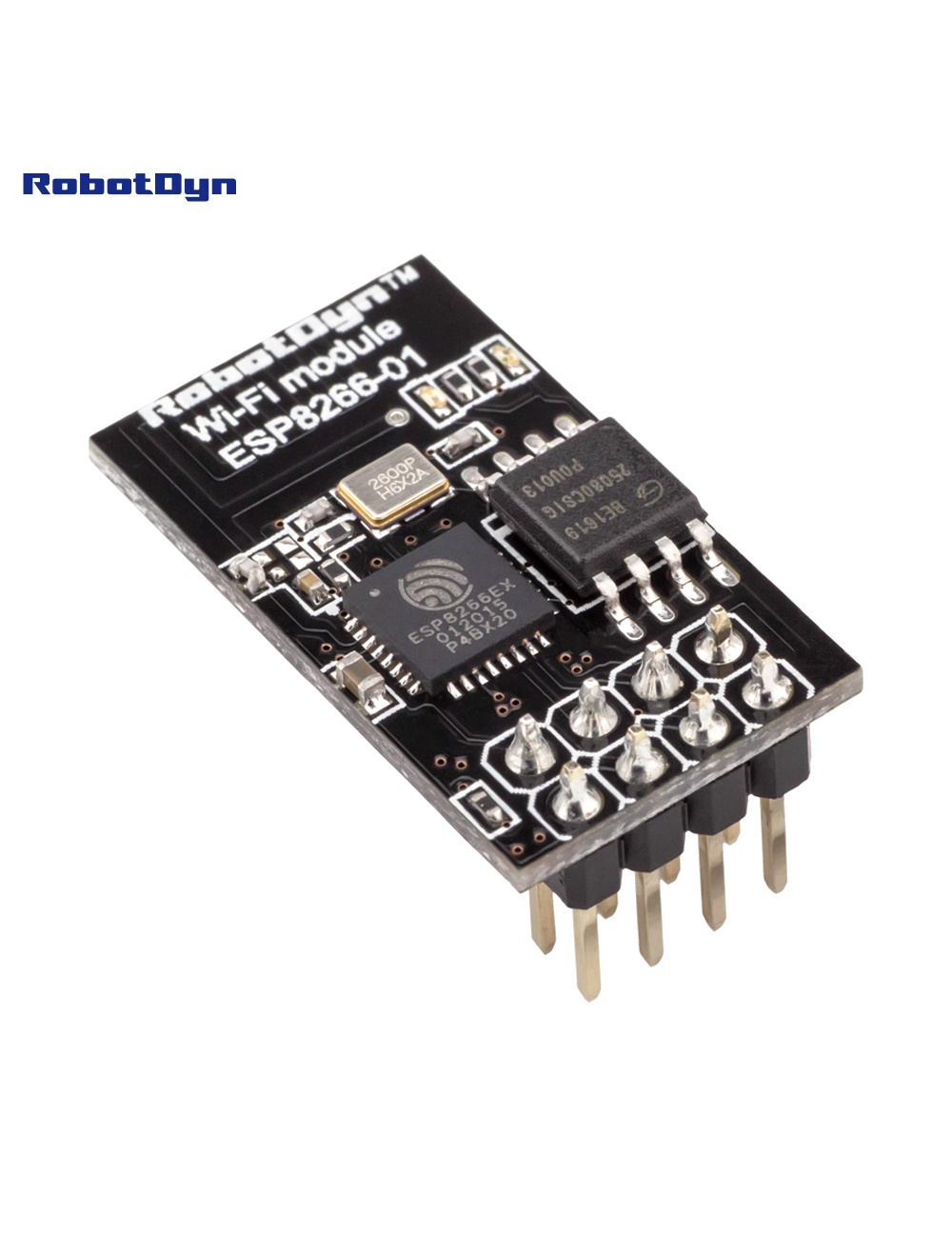
The ESP-01 is the smallest and cheapest ESP8266-based WiFi module. It comes with AT command firmware pre-installed, letting you add WiFi to any microcontroller via serial commands. Alternatively, you can reprogram it with custom firmware using the Arduino IDE, MicroPython, or NodeMCU Lua — turning it into a standalone WiFi MCU.
The footprint is just 24 × 14 mm, with 8 pins on a 2× 4 header (0.1″ pitch). Perfect for embedding in tight spaces where a full NodeMCU board won’t fit.
⚠️ 3.3 V Only
The ESP8266 is NOT 5 V-tolerant. Critical points:
- Power supply: 3.3 V only — 5V will destroy the chip
- GPIO logic levels: 3.3 V — never wire directly to a 5V Arduino’s TX without a level shifter
- Current draw: peaks at 320 mA during transmission — many 3.3V regulators on Arduino boards can’t supply this (use a dedicated AMS1117 or LDO with ≥500 mA capacity)
Pinout
        ┌───────────┐
GND  ───┤1         8├─── 3.3V
GPIO2───┤2         7├─── EN (tie to 3.3V to enable)
GPIO0───┤3         6├─── RST (pull-up for normal boot)
RX   ───┤4         5├─── TX
└───────────┘| Pin | Function |
|---|---|
| GND | Ground |
| GPIO2 | General purpose I/O (must be HIGH at boot) |
| GPIO0 | Boot mode select (HIGH = run, LOW = flash mode) |
| RX | UART receive (also GPIO3) |
| TX | UART transmit (also GPIO1) |
| RST | Reset (active LOW) |
| EN (CH_PD) | Chip enable — must be HIGH to operate |
| 3.3V | Power supply |
AT Command Mode (Default)
Connect to a USB-TTL adapter (3.3V logic only — most adapters have a 5V/3.3V jumper):
| FTDI | ESP-01 |
|---|---|
| 3.3V | VCC + EN |
| GND | GND |
| TX | RX |
| RX | TX |
Open a serial terminal at 115200 baud (some older firmware uses 9600). Send AT and you should get OK. Useful commands:
| Command | Action |
|---|---|
AT | Check responsiveness |
AT+GMR | Show firmware version |
AT+CWMODE=1 | Set to station mode |
AT+CWLAP | List available WiFi networks |
AT+CWJAP="ssid","pass" | Connect to WiFi |
AT+CIPSTART="TCP","host",80 | Open TCP connection |
Full reference: Espressif AT command set.
Reprogramming (Arduino IDE)
To use the ESP-01 as a standalone MCU:
- Wire to FTDI as above, but also pull GPIO0 to GND before powering up (flash mode)
- In Arduino IDE:
- Install ESP8266 Arduino core via Boards Manager
- Tools → Board → Generic ESP8266 Module
- Flash size: 1M (no SPIFFS) or 1M (64K SPIFFS)
- Flash mode: DOUT (important — DIO often fails on ESP-01)
- Upload your sketch
- Disconnect GPIO0 from GND, press reset — your sketch runs
Common Uses
- Adding WiFi to existing Arduino projects (via AT commands)
- Smart switches (with the ESP-01 SSR Relay)
- Tasmota / ESPHome devices in tiny enclosures
- WiFi-to-serial bridges
- ESP-NOW peer-to-peer networks (no router needed)
Tips & Quirks
- Brown-out is common — use a 470 µF capacitor across VCC/GND close to the module
- Antenna proximity — keep metal at least 5 mm away from the PCB antenna
- WiFi disabled at boot until firmware initializes — first ~500 ms there’s no connectivity
- Deep sleep wake-up requires soldering GPIO16 → RST (not broken out on ESP-01)
Related Products
- ESP-01 SSR AC Relay — fits this module
- WiFi NodeM ESP8266 32M — full NodeMCU with USB
Documentation
- Pinout PDF — coming soon
- AT command quick reference — coming soon
- Reprogramming guide — coming soon